Our system revolutionizes the way the industry functions. We capture the exact weight of gas to the point of .050 gms at any given point of time. Our system alerts customers when the gas percent reaches the threshold level as defined by the customer depending on their needs. This ensures 100% accurate safety to fight fire accidents on time (every time). Our system overcomes the deficiency of the existing practice of manual weighing of cylinders.
Previous systems there was no proper weight and reports in the cylinder of Low Gas Alert Monitoring System in fire and safety industries. Now we Introducing our company New Technology system with proper 24/7 continuously on, this system shows the total cylinder weight with the following features:
1.
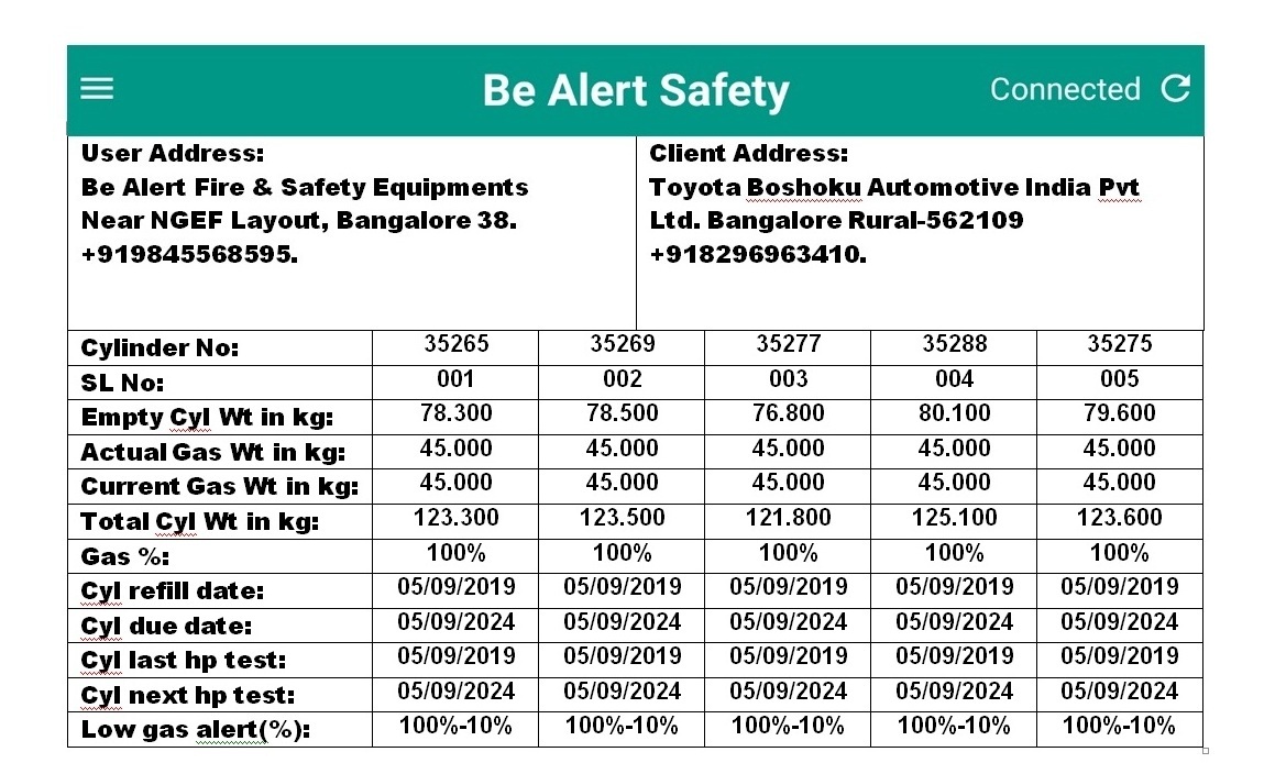
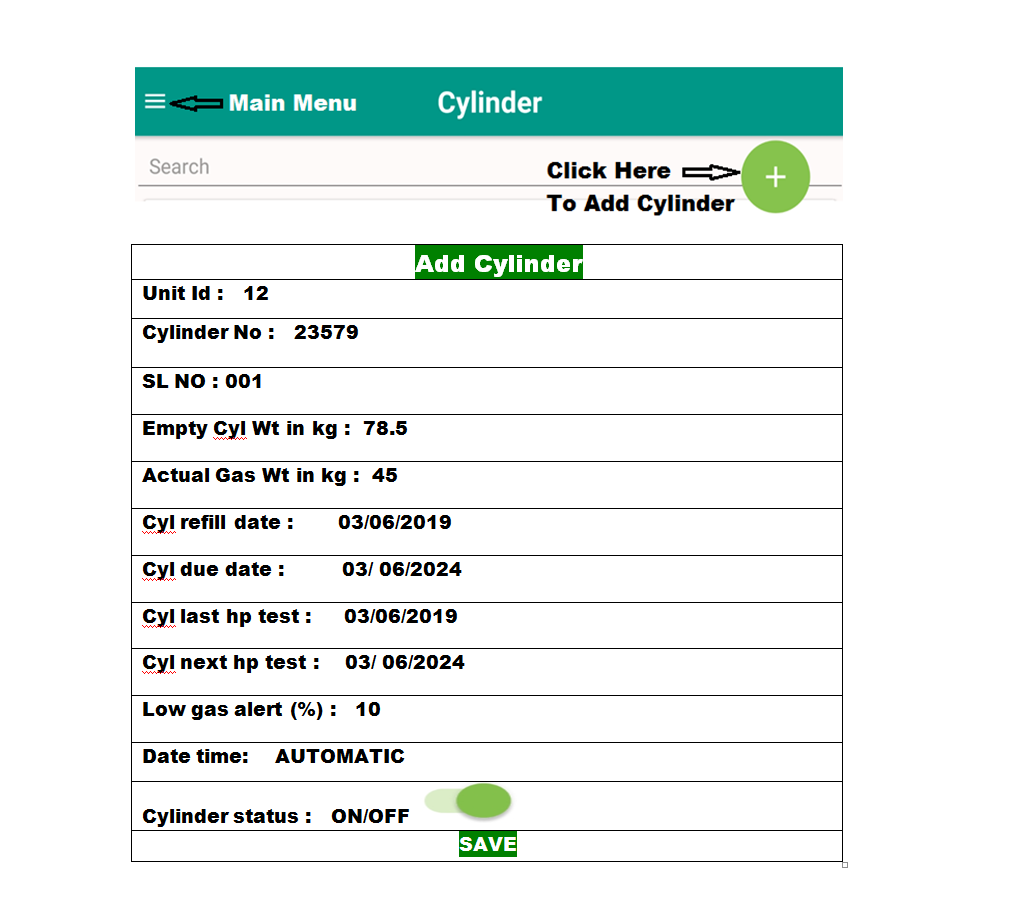
Exact weight of Empty cylinder weight, Gas weight, Total weight, Refilling date, Refilling due date, HP test date, HP test due date and cylinder serial no is given at point of time.
2.
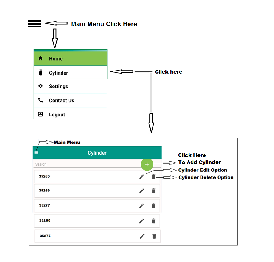
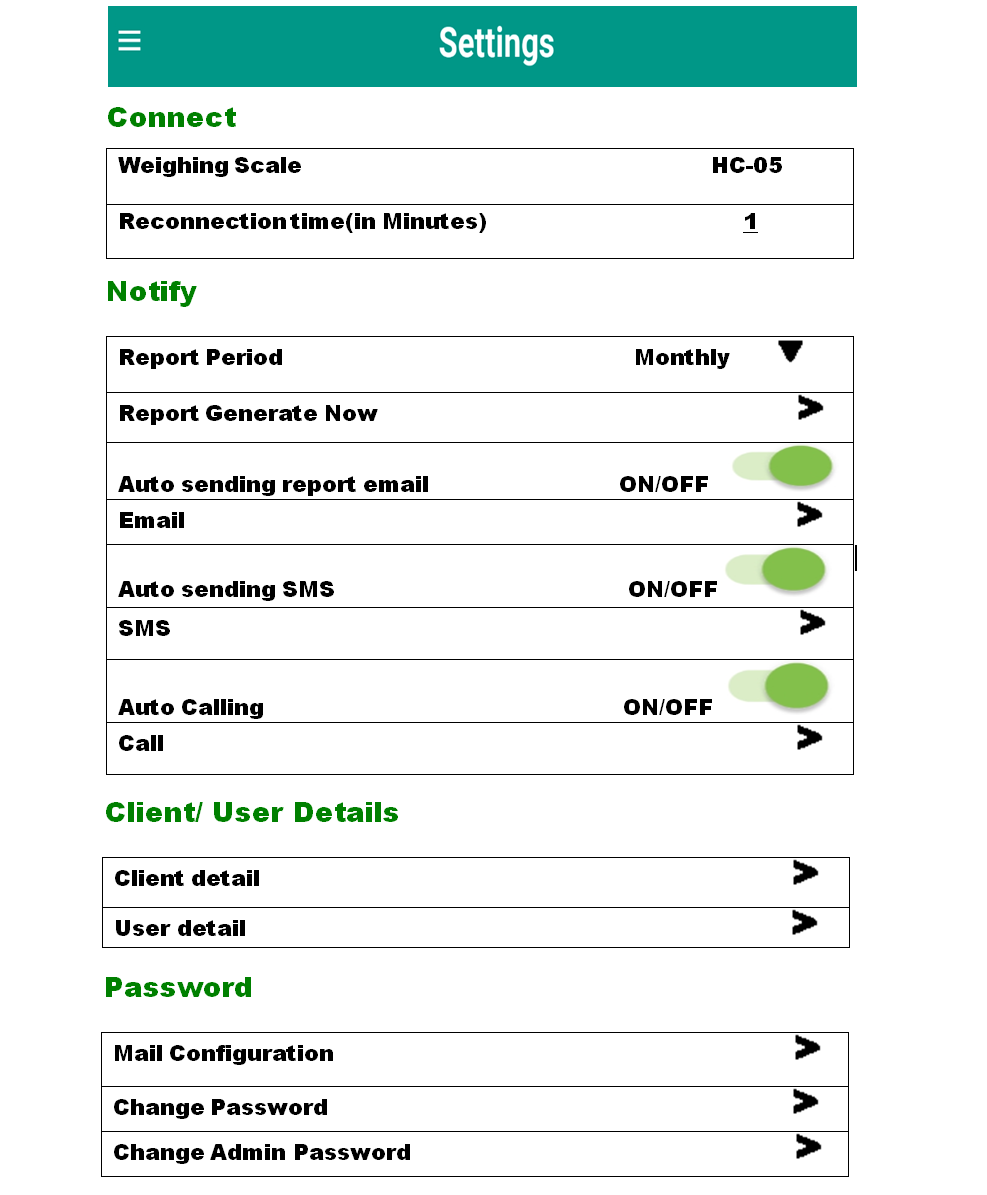
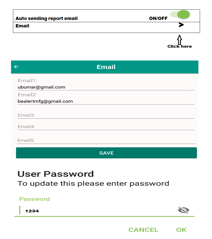
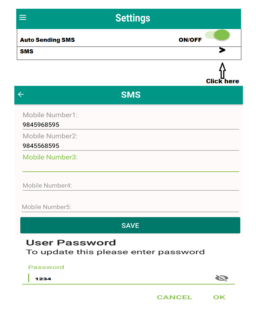
This system sends Email and SMS when the cylinder gas is low at (10%).
3.
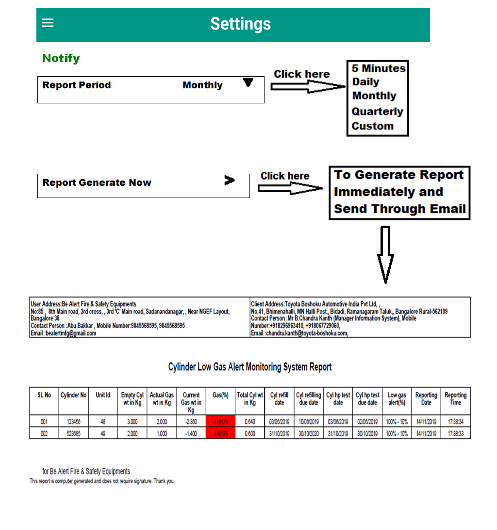
Report can be generated automatically (Monthly, Quarterly or immediately) with exact date and time.
4.
This system is 4G SIM based GSM android application with LCD Touch Screen panel.
5.
The received data sheet from Email can be printed using A4 sheet.
6.
Email and mobile number’s can be added to receive data (maximum 5 numbers).
7.
Signature is not required for report, it is system generated.
8.
Load cell sensitivity is accurate.
9.
Facility of System connection to fire alarm panel (module trough).
10.
Hooter option is also available for low gas alert.
11.
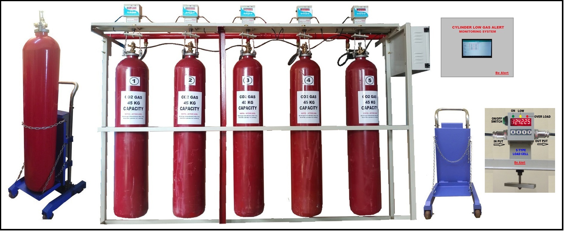
System show Red color if particular cylinder gas is low.
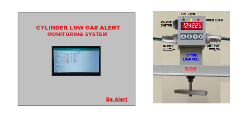
CYLINDER LOW GAS ALERT MONITORING SYSTEM
CONTROL PANEL LCD TOUCH SCREEN
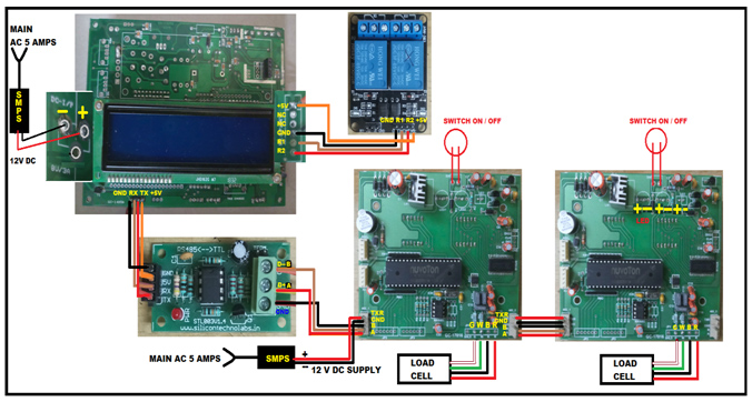
MAIN DISPLAY BOARD, UNIT BOARD, RELAY BOARD FULL DIAGRAM
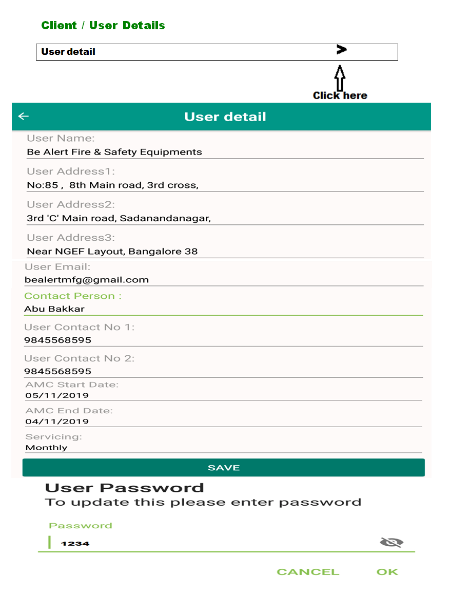
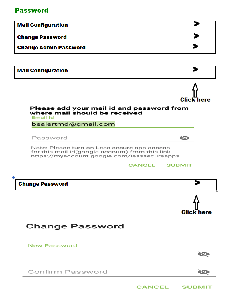
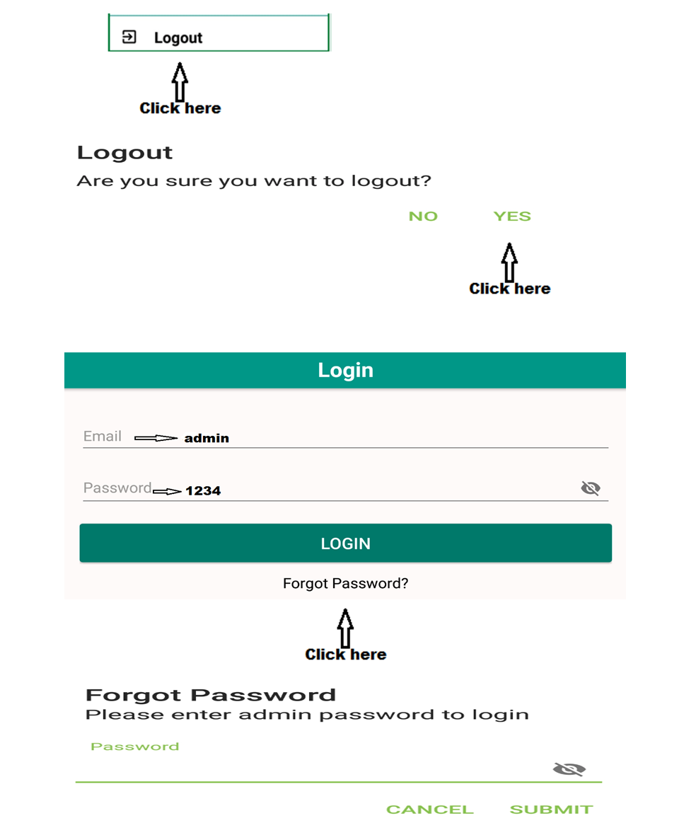
CYLINDER LOW GAS ALERT MONITORING SYSTEM
USER MANUAL GUIDE
NEW TECHNOLOGY
Mother Board Technical Specification
TECHNICAL SPECIFICATION:-
MCU:- Nuvoton based microcontroller with internal EEPROM IC and crystal for lower maintenance and higher life of the IC.
ADC:- The mother card uses latest AVIA technology based HX710, 24 bit delta sigma ADC for higher resolution, for better accuracy and better linearity. ADC is also has internal crystal so reduce the chance for crystal failure errors with found in last decade
1.
Supply Voltage:– 230V AC, 50Hz +/- 10% (12 V DC Output supply 5 Amp)
2.
Operating Temperature:– 0 Degree C to 45 Degree c.
3.
Humidity: 10% to 95% relative humanity (Non condensing).
4.
Power consumption: Max 10 watt.
5.
Hysteresis:- 0.03% of Rated capacity.
6.
Linearity:- 99.9% of the Rated capacity.
FEATURES:-
1.
The card has internal 16,000,000 Counts and 292,000 Display Count.
2.
Advance micro controller based technology.
3.
Auto power saver.
4.
The Full 6 Digits can be utilized with and without Dummy Zero.
5.
Card is also run if the initial count of the Load cell should be in negative (i.e. Minus zeroing).
6.
The best battery backup then the other card.
7.
18 Digits Alphanumeric NAME Setting.
KEYS:-
There are 4 keys function in the mother board.
Key 1:
Tare KEY / Enter
Key 2:
INCREMENT / Name SETTING
Key 3:
SHIFT / PARAM SETTING /CAL PRESS
Key 4:
COUNT / CAL ENTER
PARAMETER SETTINGS:-
Steps:
1.
1st Switch OFF the Scale, then Press & hold KEY3 (CAL PRESS / SHIFT) & switch on the scale.
2.
“PASS “ -> Key1 -> “ADDRES”->key1
3.
Enter address by key2 and key3. - > key1
4.
“CAPCTY”-> KEY1->Enter scale capacity by key2 and key3 -> KEY1
5.
“ACC “-> Key1 -> select accuracy by key2 -> key1
6.
“DP “-> select decimal point location by key2 (DP position 0 rightmost digit) -> kEy1
7.
“AUTO “->select auto zero setting by key2 (AUTO zero is weight when fluction when weight is zero it shows zero value)
8.
DONE
DISPLAY INTERNAL COUNT:-
For displaying internal ADC count. Switch ON SCALE by pressing KEY4 (CAL ENTER/ COUNT). Release the KEY display show internal ADC COUNTS.
To exits from counts press KEY2 (MODE /INCREMENT).
CALIBRATION:-
Calibration can be done in weighing mode,
Steps:
1.
First On/Start the weighing scale. Press KEY1 (TARE) for TARING the weight.
2.
Put the standard weight on the scale, weight should be 1/3rd of the Full capacity.
3.
Then press & hold KEY3 (CAL PRESS / SHIFT) & press once KEY4 (CAL ENTER / COUNT). Display shows “PASS”. Enter the parameter lock password with the help of KEY2 (MODE / INCREMENT) and KEY3 (CAL PRESS / SHIFT) then press KEY1 (TARE).
4.
Display shows “CAL” Press KEY1 (TARE). Then display show the count changed. Then display shows “000000”.
5.
Now enter the weight by incrementing KEY2 (MODE / INCREMENT) and KEY3 (CAL PRESS / SHIFT) for Shifting.
(E.g. If putted standard weight is 2Kg, to enter 2000. when display shows 000000
Then press KEY2 (MODE / INCREMENT) key two times so that display shows “000002” now press KEY3 (CAL PRESS / SHIFT), 3 times so the display shows “002000”).
6.
Now Press KEY1 (TARE) key. Calibration is Successfully done.
LCD BOARD:
Setting of weight
Switch off system, switch on scale by pressing key2.
“No of cyl” -> key1 -> enter no of cylinder key2 and key3-> key1
“Address of cyl XXX” -> (where XXX is cylinder number) Enter address by key2 & key3 -> key1
Once done all setting done.
Please check address of weighing machine, same address should added here and also touch based system.
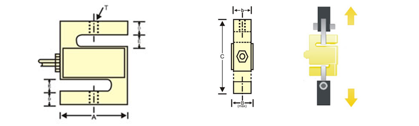
S-Type Load Cell – Specification 500 kg Capacity
| Description : |
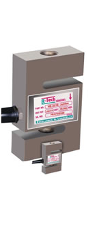 |
Model HE-2210-T is a High Precision Strain Gage based the‘S’-beam Load Cell
The ‘S’-beam Load Cell is Versatile, compact and rugged.
It is used for tension / tensile testing, weighing, industrial automation
and research applications.
It is universal Load Cell Suitable for both-tension and compression modes.
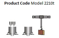
Applications :
Industrial Automation
Tank, Hopper, Bag Weighing, Hanging & Crane Scales
Conversion from Mechanical Scale/ Weigh Bridge
Force Measurements ( Testing Machines)
Tension Or Compression
|
| Features: |
 |
Alloy Tool Steel construction for resistance against shock and overload.
Complete Environmental Protection -IP67 class.
Standard output (3.0 mV/V + 0.25% ) available on request
Standard output (2.0 mV/V+ 0.25% ) available on request
Custom built design available on request.
|
| CAPACITY Kg. |
A |
B |
C |
D |
T |
D |
E |
Toruue m. kg. |
Cable Length Mtrs. |
| 20 to 100 |
50 |
20 |
12.5 |
62 |
M6 x 1.00 |
10 |
9 |
0.25 |
5 |
| 150 to 1000 |
50 |
25 |
19 |
62 |
M12 X 1.25 |
10 |
9 |
0.25 |
5 |
| 1500 to 3000 |
75 |
33 |
27 |
100 |
M20 X 1.50 |
17 |
9 |
2.00 |
5 |
| 5000 to 7500 |
90 |
40 |
32 |
140 |
M24 X 2.00 |
25 |
9 |
9.00 |
10 |
| 10000 |
112 |
52 |
45 |
175 |
M30 X 2.00 |
40 |
13 |
10.00 |
20 |
| 15000 to 20000 |
150 |
72 |
65 |
250 |
M36 X 3.00 |
60 |
13 |
12.00 |
20 |
Specification
| STANDARD CAPACITIES |
50,75,100,150,200,250,300,500,
750,1T,
1.5T,2T,2.5T,3T,5T,10T,15T,20T.
|
| EXCITATION VOLATAGE |
10VDC TO 15VDC |
| RATED OUTPUT |
2.0 mv/v |
| INPUT RESISTANCE |
392 +- 10 Ohms |
| OUTPUT RESISTANCE |
350 +- 3.0 Ohms |
| CREEP (30 MINUTES) |
<+- 0.03% Fso |
| ZERO BALANCE |
+-1.0% Fso |
| NON-REPEATABILITY |
<+-0.01% Fso |
| HYSTERESIS |
<+-0.02% Fso |
| NON-LINEARITY |
<+-0.25% Fso |
| SAFE OVER LOAD |
150% Of Rated Capacity |
| ULTIMATE OVER LOAD |
250% Of Rated Capacity |
| ALLOWABLE SIDE LOAD |
50% Of Rated Capacity |
| TEMPERATURE EFFECT ON O.P. |
<0.0015% Fso% oC |
| TEMPERATURE EFFECT ON ZERO |
<0.0020% Fso% oC |
| ENVIRONMENTAL PROTECTION |
IP67 |